Test Objective: Test the WB7AEI Audio Filter bandwidth with it integrated into my W1FB DC Receiver. The filter is inserted between the audio pre-amp and the LM386 audio amp.
Background:
I used the K2 transmitter set at approx 100mW transmit on the test frequency of 7020KHz.
I leaked some signal through the connection to a TEE piece of a piece of wire approx 12inches long. The RX was connected to a 51 ohm load in order to ensure proper matching of the input stage.
Test information and process.
- Headphone DC resistance = 12.3ohms
- Signal strength adjusted in the receiver for normal listening levels using terminated K2 as the signal source.
- Vcc= 10.9v
- Connected 1X probe to the speaker connection and used Channel 1 set at 50mV per division.
- Adjusted volume control for a peak to peak signal of 8 divisions while peaking the audio filter and input filter. Adjusted the receiver to give an approx 700Hz tone.
- Recorded the peak audio frequency at about 677Hz.
- Then tweeked the receiver trimmer for a peak to peak signal of 4 Divisions on the scope.
- Recorded the audio frequency at approx 637Hz.
- This yields a -6dB point bandwidth of 2X(677-637) = 80Hz.
- The design spec of the filter quotes a calculated 3dB bandwidth of 32Hz. This I concluded that the filter is working within spec.
TEST ISSUES:
- The receiver oscillator is not stable enough to obtain better more accurate readings.
- The signal coupling should be through an attenuator to better be able to stabilize the input signal level.
- More work is needed to improve the VFO stability for sure.
 |
| W1FB Receiver showing connection of 51OHM resistor to the antenna input |
 |
| Rear of the K2 showing TEE piece and dummy load for signal leak |
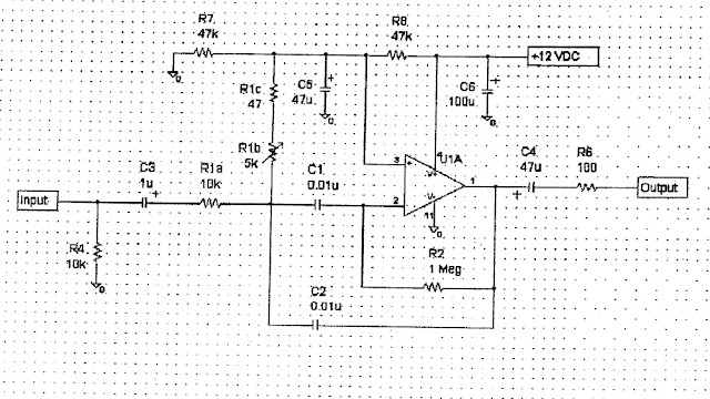 |
| WB7AEI Tunable Audio Filter. BW at -6dB ~ 80Hz. ie in spec. |
