02 October 2013

ZS6RSH Prototype Field Rig

Herewith some pics of the breadboard rig so far, and based on the W7ZOI Universal QRP rig with 1.5 watts output and Xtal controlled for 7020Khz.

The Rx is from W1FB's QRP notebook and using the ubiquitous NE602 mixer/oscillator. The oscillator is very stable and I now have a good RIT type tuning capability. Measurements to follow.

The control board has a sidetone multivibrator oscillator. The sidetone is routed through the very sharp active audio filter which improves the sidetone quality. Still room for improvement.

There is an active audio filter installed (specs to follow). This filter is tunable and works well in conjunction with the RIT type tuning control to optimize signal reception.

There is still much room for improvement. However the scope must be kept limited to the original objective which is a very simple rig that can be used for NVIS operations during daylight hours on short walks to the park over the weekend.

Room for improvement:

  1. Still a loud pop in my ear on T/R. Need to improve the changeover.
  2. Build a mini-boots to take it up to 5 watts
  3. Install a keyer chip
  4. Try a passive audio filter. Have a design from ZS4SF which has a nice 900Hz bandwidth. The one I am using is a bit sharp for this application under some band conditions.
  5. Install all in a rugged field box.
L-R. Audio Filter, DC Rx, Control/Sidetone, Tx-1.5W


01 October 2013

2N3553 Power Transistor Measurements

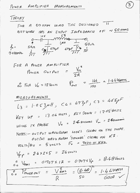
Looking at the Phillips data sheet for the 2N3553 transistor and then trying to compare the measurements I took for my 1.5Watt 40m transmitter based on W7ZOI design,  as follows:

Note: I am certainly not sure if the measurements are correct? Further analysis needed.

2N3553 is an NPN RF power transistor intended for VHF applications and recommended by W7ZOI as being suitable for the Universal QRP Transmitter (1.5Watts). He states that even under high SWR conditions the transistor will survive. I have not tested this (although I would love to) since I only have one of these transistors and they are quite expensive.

Case Type = TO-39. (I am running mine with no heatsink although it does get a little warm when sending normal type CW)


Vceo (Peak Collector Emitter voltage) = 40v max. My Vp-p on a 50 ohm load is 24volts (this as expected)
Icm (Peak Collector Current) = 1A. My Ic rms value is 213mA. Thus my Ic peak is 315mA. (not certain)
Ptot = 7W. This is max power dissipation. My tx has a calculated power dissipation of 1.5Watts. ie well below the rated max value and probably explains why it can run with high SWR? The spec also states an efficiency of 50%. I measured an efficiency of 53% which appears to be in the ballpark.

According to the spec. For f=175Mhz. Vce=28, Po = 2.5Watts and Gain = >10dB.

I measured as follows: f=7.020Mhz, Vce=24, Po=1.5Watts and Gain = 18dB. Seems reasonable??

29 September 2013

A Universal QRP Transmitter by W7ZOI. My Version


Oscillator Output into 39Ohms

Oscillator rubbered frequency

08 September 2013

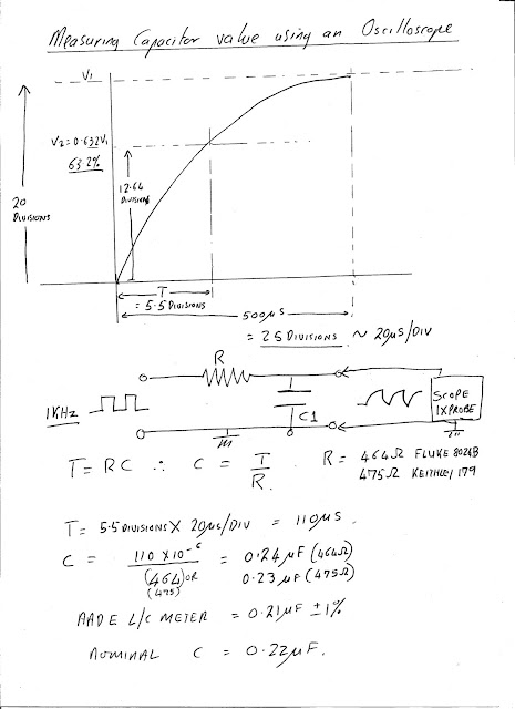
Measuring Capacitor values with a Scope

R=470ohms, T=110us. C=0.22uf

F=1Khz

Testing Bipolar Transistors


  1. Obtain a silicon diode, simple analog ohmmeter or DMM, test leads, 100K resistor & mystery bipolar transistor
  2. Set the ohmmeter to a low resistor reading scale
  3. Identify which is the positive lead and which is the negative lead by forward biasing the diode
  4. Identify the Base as the lead on the transistor that is common to the Collector/Emitter in the forward bias condition.
  5. If the Base is negative then it is a PNP transistor. If it is positive then it is NPN.
  6. Take a guess. Connect the test leads to the Emitter/Collector
    1. Forward bias the transistor by connecting the 100k resistor between Base and Collector by guessing which is the Collector. The forward bias condition is seen as the ohmmeter showing a low resistance reading.
    2. For a PNP transistor the Emitter will be connected to the positive lead.
    3. For an NPN transistor the Emitter will be connected to the negative lead

09 August 2013

Impedance looking into a short coax test lead. What is it?

It is certainly not intuitively obvious to me why the capacitance looking into a coax 50ohm test lead is not factored into account when terminated in the characteristic impedance Zo.

Below shows my confusion.

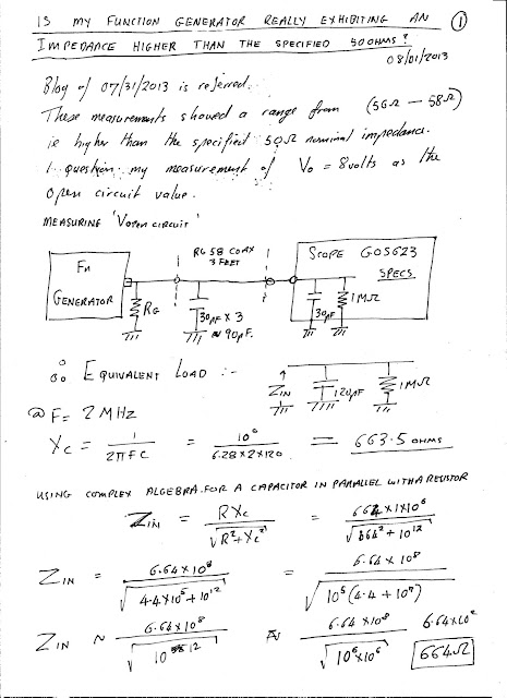
Why in the case of  the model in Figure 1 would I take the capacitance of the coax into account? (about 30pf per foot) when I terminate in a high impedance? Yet when I terminate the coax in a 50ohm load in the model in  Figure 2 I do not see the capacitance? In other words the model in Figure 3 is incorrect.

Even at a frequency of 2MHz the calculated impedance Zin in Figure 1 is 664ohms magnitude, of course with some phase shift. This means that the capacitive effect of the 3ft coax connecting cable is significant.

Some study of transmission lines is needed to reveal the answer.


03 August 2013

Function Generator Output Impedance Calculation

I Question my Function Generator Impedance Measurements