Reference The CMoy headphone amplifier details
Gain and DC offset measurements were made using two different rail voltages as follows:
Input signal: A sinewave at 1kHz with variable amplitude. Source impedance = 50ohms.
Load: 270ohms on each channel to (simplistically) simulate the Beyerdynamic DT880 audiophile headphones owned by my son.
Both channels showed the same results.
LED current = 1.43mA
With rail-to-rail voltage = 7.68V, DC current = 9.1mA. (Same w/wo the 270ohm loads connected). Thus DC power = 70mW.
Vgnd-Vplus = 3.77V. Vgnd-Vneg = -3.91V. Thus DC Offset = (7.68/2)-3.77=70mV.
At the point of clipping on positive voltage swings Vp-p(out) = 4.6V. Vp-p(in) = 430mV.
Thus Vgain = 10.69. Headroom on the Vplus rail = |(4.6/2)-3.77|=1.47V.
P=(Vp-p)^2/8R = 4.6^2/(8*270)=9.7mW.
Thus efficiency = 9.7/70 = 0.14.
With rail-to-rail voltage = 15.31V. DC current = 11mA. (Same w/wo the 270ohm loads connected). Thus DC power = 168mW.
Vgnd-Vplus = 7.59V. Vgnd-Vneg = -7.72V. Thus DC Offset = (15.31/2)-7.59=65mV.
At the point of clipping on positive voltage swings Vp-p(out) = 10.9V. Vp-p(in) = 1V.
Thus Vgain = 10.9. Headroom on the Vplus rail = |(10.9/2)-7.59|=2.14V.
P=(Vp-p)^2/8R = 10.9^2/(8*270)=55mW.
Thus efficiency = 55/168 = 0.33
18 August 2015

14 August 2015
CMoy pocket Headphone amplifier. Input coupling capacitor tests
My son recently became the proud owner of a pair of audiophile headphones. A pair of Beyerdynamic DT880 premiums. See the specs http://zs6rsh.blogspot.com/2015/07/headset-technical-specification.html

Motivated by my friend Chris KD4PBJ, I built a prototype of the CMoy pocket headphone amplifier. As specified, I used an OPA 2132PA Burr-Brown Op Amp. The rest of the components came out of my junkbox.
In reading the section on Input Capacitors for Headphone Amps, the author recommends the use of Polypropylene Film Capacitors as the best choice followed by Polyester Capacitors and to stay well away from Ceramic Capacitors. A very interesting read. I understand that a major issue in audiophile amps with AC coupling is Phase Distortion caused by the low frequency roll-off due to the RC high pass filter formed by the coupling capacitor and the amplifier input impedance. This causes a smearing of the Bass notes due to Phase delay from about 10Hz through 100Hz for a 0.1uF input coupling capacitor looking into an input impedance of 100Kohms.
Curious about this, I set up a test fixture to measure the phase distortion differences between what looked like a film poly capacitor in my junkbox (and which I deployed in my prototype) and a ceramic capacitor. I also ran an ideal model using LT spice.
The high pass RC filter measured, consisted of the 0.1uF test capacitor and a 100Kohm resistor. As input I used a function generator set to approx 20mVp-p sinewave and two 10X probes connected to an oscilloscope to measure the phase delay between the input and output of the circuit. Lissajous figures were used to measure the phase angle to approximately a plus/minus 2 degree accuracy.
Attached find a graph of the plotted result. I noted that the measured -3dB filter knee for the poly capacitor was 17Hz plus/minus 2 Hz and the ceramic was 21Hz plus/minus 2Hz.
As can be seen, I was unable to measure a big difference in the phase delay of these capacitors using my 1970's era home lab equipment. The measured results compare favorably with the ideal capacitor phase delay calculated results.
In delving into the fascinating world of the audiophile at http://www.head-fi.org/ I came to realize that what constitutes a 'good sonic' is something highly complex and thus, highly subjective. So what is it that makes a polypropylene film capacitor 'sound' better than a ceramic capacitor? It is not revealed in my simplistic measurements. Perhaps driving the amp with a step signal (squarewave) would reveal much more about the differences in these capacitors?
The amp works very well with the DT880's to my ear although clipping of Bass notes was noticed when driven with 9volts. No clipping when using an 18volt source. Leading to an idea to build a buffer type virtual ground for the next version.
Thanks to the excellent website http://www.tangentsoft.net/, I have experienced a glimpse into the complex world of the audiophile.
Now can I use one of these amplifiers to replace an LM386 in my regen receiver? :)
 |
| CMoy Prototype 1. The input and outputs should be isolated from the chassis! |
 |
| The junkbox Wesco input capacitors can be seen. Next version needs 18volts to drive the DT880's. The Op Amp is a Burr-Brown OPA2132PA. Amazing sound! Zero hiss. |

 |
| RC Network High Pass Filter test fixture. Input = 200mVp-p sinewave from a Function Generator (50ohm source impedance). Phase angles were measured using Lissajous figures. 10X scope probes used. |
04 August 2015
Adventure Radio Society Spartan Sprint August 2015
Great fun was had in the Spartan Sprint Contest last night Monday evening. Spartan Sprint Rules.
I operated my old trusty ATS3 rig into a BLTuner feeding an inverted Vee 80m doublet up about 55ft at the apex. Power output at the beginning of the contest was 2Watts on 40m and 20m. The battery was a 750mAH Li Po battery as the power with a set of mini paddles and earbuds. The total weight for this setup was 13.4oz (0.838lbs) of which 7oz was attributed to the ATU! There is definitely room for improvement and weight loss with my station.
QTH is near Raleigh NC operating from the kitchen table since it was extremely hot outside.
Band conditions were good and I was able to work all stations copied. 20m was excellent for the first hour and then switched to 40m. QRN was high on 40m but the signals were strong. Towards the last 30 minutes I switched back to 20m but no signals were copied. In particular I enjoyed the contacts with N4SX (1 Watt on 40m in GA) and KA5QQA (1 Watt on 20m in TX).
Thanks to all for another great Spartan Sprint evening.
RESULTS
Total weight = 13.40oz = 0.838lbs
20m QSOs = 15
40m QSO's = 11
Total QSO's = 26
QSO's per Lb = 31.03


28 July 2015
Flight of the Bumblebees 2015. N4HAY. Jordan Lake NC
I really enjoyed the FOBB this year. Unlike last year the bands were in good shape and the wx was beautifully mild. I set up in roughly the same spot as last year only this time I deployed a far superior antenna system. My operation did not involve a major trek since I merely walked from the car park to a nearby picnic table. Oh well perhaps next year I will commit to more of an adventure hi.
The FOBB was held on Sunday afternoon from 1pm - 5pm Eastern time zone. Check out the following link for The Adventure Radio Society Flight of the Bumblebees details of the contest rules.
I set up at the Ebeneezer State Park at Jordan Lake North Carolina. This is about a 20minute drive from my QTH. I arrived on site at noon. First I had to build a 40m dipole. I was not well prepared for this contest! I then deployed my 20m and 40m dipoles. This turned out to be more of a challenge than I had judged. Thus I was only QRV an hour into the contest. However once my antennas were deployed they were very effective. My 40m dipole was beaming N-S and was up about 55 ft agl. My 20m dipole was beaming W-E and was up about 45ft. I used my trusty slingshot to launch the antennas to this height.
Rig was a K2 running on the internal battery. I ran a frequency and S&P about 50/50. Battery indicated voltage on the K2 was down to 11volts by the end of the contest.
Band conditions were good and I was able to work almost all stations that I heard. I had the feeling that I could have done better with a W-E facing 40m dipole. Lesson learnt here was to stick to a simple inverted-vee doublet center-fed with ladder line next time. Ideally deployed in such a way that I could change the orientation easily. I am sure I could have done better if I had been better prepared.
I also had problems with my pen that would not write properly! This brings to mind the reason why early astronauts used pencils on their early missions hi!
I was unable to copy my fellow Knights from the Knightlites QRP club Sirs Derek W4FI, JP AB4PP and Paul AA4XX indicating that the 40m band was long.
I look forward to next year's adventure with much anticipation. Many thanks to all stations who worked N4HAY. 72 de Dick.
Log of N4HAY. FOBB 2015. Jordan Lake
 |
| N4HAY. FOBB 2015. Suffering no pain! |
24 July 2015
Headset Technical Specification comparison
I did a little technical comparison, based on online technical specifications, between the shown headsets. I found it interesting. Perhaps not surprising. On a qualitative level I note a 'very big' difference in sensitivity between the David Clarks and my Sennheisers. However I assume that I am driving them with an amplifier (a current audio amplifier in my Elecraft K2 ham radio) and may not necessarily be optimized for either.
Headset technical comparison
I also do notice a difference in both low and high range frequencies between my Sennheiser and Earpods on listening tests. But still the Earpods are very very good and have to be some of the best value for money on the planet?
I would say that all 3 headphones would benefit from a Headphone Amplifier.
Also note that the SPL measurement is made at one frequency only. Generally seems to be 1KHz. So the sensitivity may seriously degrade at the ends of the claimed bandwidth.
It is interesting to note the technical differences between the sets as optimized for different applications.
Given the complexity of comparing headphones due to many parameters way beyond this list I would think that the 'crowd sourcing' method of opinions may be the best way to make a determination as to which headset is best for you.
Headset technical comparison
18 July 2015
Field Day 2015. WQ4RP. The Knightlites
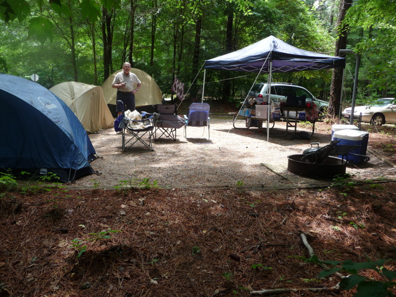
As in all previous years for me, Field Day 2015 with The Knightlites was a total pleasure! A great adventure and an opportunity to learn and appreciate the challenges presented from operating in the great outdoors in less than ideal circumstances. Certainly that was the case this year!
Four intrepid Knights Sirs Derek W4FI, Joe WA4GIR, JP AB4PP and Dick N4HAY operated Field Day as WQ4RP, Class 3A Battery, NC from the Holly Point State Park at Falls Lake North Carolina.
 |
| The Great Setup. Pics by Joe WA4GIR |
 |
| Sir JP and Sir Derek before the action began. Pic by W4CHX Karl |
Violent thunderstorms on Friday evening, and Saturday, destroyed a tent and relegated some of the Knights to sleeping in their cars. But the intrepid few remained at the Key...Sending and Receiving in spite of it all! Great adventure, camaraderie and plain good fun was had for sure.
Some finer details of the event.
Background
Results
Operating Conditions
Lessons Learned
Inventory Checklist
DUP Sheet
Here find Band analytical information:
10 meters
15 meters
20 meters
40 meters
80 meters
All Bands
 |
| MRE's issued by Sir JP just in case. Pic by W4CHX Karl |
 |
| A shelter destroyed by a violent thunderstorm. Pic by JP AB4PP |
 |
| 20m operating position. |
 |
| 20m operation position. Pic by Joe WA4GIR |
 |
| Sir Derek WF4I pounding the key on 20m on Sunday morning |
 |
| 40M operating position. Pics Joe WA4GIR |
 |
| Sir JP at the key. 80m, 15m, 10m operating position. Pic by Joe WA4GIR |
 |
| Mason (or Consul) Jar LED lamp. A South African product |
 |
| The Knight's Trebuchet built by Sir Gary N3GO. This weapon gave us at least a 3dB advantage! |
Background
Results
Operating Conditions
Lessons Learned
Inventory Checklist
DUP Sheet
Here find Band analytical information:
10 meters
15 meters
20 meters
40 meters
80 meters
All Bands
 |
| WQ4RP The Knightlites. Field Day 2015 QTH. Pic by W4CHX Karl |
09 January 2015
Homebrew Attenuator Measurements contd
It was interesting to measure the insertion loss and maximum attenuator accuracy over a wider frequency range.
The BIG attenuator has a maximum attenuation of 68dB.
The Copper attenuator has a maximum attenuation of 71dB.
As for the previous measurements I used the HP 8657B as the 'standard' against which to compare.
I also used a 0dBm input level for the 71dB (copper attenuator) and 68dB (Big attenuator) measurements in order to move the measurements comfortably up from the lower end of the Power Meter measuring capability. The Power Meter in fact showed a consistent slope ranging from 20.5mV/dB for 1.6MHz to 19.69 mV/dB at 450 MHz. Quite cool for a homebrew power meter!
Reference the following links:
68dB slope calculation
Insertion Loss Measurements
Maximum Attenuation Measurements
In conclusion both attenuators show significant insertion loss and maximum attenuator errors for the 148MHz, 224MHz and 450MHz measurements.
 |
| 'BIG' Attenuator |
 |
| 'Copper' Attenuator |
Subscribe to:
Posts (Atom)