AWA CW net Saturday June 29th
The net on Saturday was particularly good. Band conditions were the best we have heard for some time. All station were 599+ including Derek ZS5DM who is usually an S point or two down. The exception was ZS1JX Peter who I copied 589. However given that he is in Cape Town this was a very good report. Peter also gave me a 579 on my QRP signal which was really pleasing. Peter came back for a round using 100mW QRPp. Amazingly Andy, Barrie and myself could hear Peter's signal just at noise level. He was a good 449. Helping Peter was the fact that he has a great antenna system. I copied a Vee Beam for his transmitter and beverages for his receiver. Very FB and I hope we will copy Peter again. Stations reporting into the net included:
ZS0AWA / ZS6ADY - Andy, Benoni net control
ZS1AJX - Peter, Worcester
ZS6AJY - Barrie, Benoni
ZS6JBJ - John, Witbank
ZS6RSH/QRP, Dick, Fourways
ZS5DM - Derek, Kloof, KZN
30 June 2013

29 June 2013
WB7AEI Audio Filter Bandwidth tests
Test Objective: Test the WB7AEI Audio Filter bandwidth with it integrated into my W1FB DC Receiver. The filter is inserted between the audio pre-amp and the LM386 audio amp.
Background:
I used the K2 transmitter set at approx 100mW transmit on the test frequency of 7020KHz.
I leaked some signal through the connection to a TEE piece of a piece of wire approx 12inches long. The RX was connected to a 51 ohm load in order to ensure proper matching of the input stage.
Test information and process.
Test Objective: Test the WB7AEI Audio Filter bandwidth with it integrated into my W1FB DC Receiver. The filter is inserted between the audio pre-amp and the LM386 audio amp.
Background:
I used the K2 transmitter set at approx 100mW transmit on the test frequency of 7020KHz.
I leaked some signal through the connection to a TEE piece of a piece of wire approx 12inches long. The RX was connected to a 51 ohm load in order to ensure proper matching of the input stage.
Test information and process.
- Headphone DC resistance = 12.3ohms
- Signal strength adjusted in the receiver for normal listening levels using terminated K2 as the signal source.
- Vcc= 10.9v
- Connected 1X probe to the speaker connection and used Channel 1 set at 50mV per division.
- Adjusted volume control for a peak to peak signal of 8 divisions while peaking the audio filter and input filter. Adjusted the receiver to give an approx 700Hz tone.
- Recorded the peak audio frequency at about 677Hz.
- Then tweeked the receiver trimmer for a peak to peak signal of 4 Divisions on the scope.
- Recorded the audio frequency at approx 637Hz.
- This yields a -6dB point bandwidth of 2X(677-637) = 80Hz.
- The design spec of the filter quotes a calculated 3dB bandwidth of 32Hz. This I concluded that the filter is working within spec.
TEST ISSUES:
- The receiver oscillator is not stable enough to obtain better more accurate readings.
- The signal coupling should be through an attenuator to better be able to stabilize the input signal level.
- More work is needed to improve the VFO stability for sure.
 |
| W1FB Receiver showing connection of 51OHM resistor to the antenna input |
 |
| Rear of the K2 showing TEE piece and dummy load for signal leak |
 |
| WB7AEI Tunable Audio Filter. BW at -6dB ~ 80Hz. ie in spec. |
28 June 2013
The effect of supply voltage on transmitter output power.
My friend Monk related an interesting experience where his battery charger has an intermittent fault. Meaning that the actual voltage being supplied to his QRP transmitter was varying. This was resulting in inexplicable power output variations in his transmitter.
I calculated that in his case a variation in Vcc from 13.7volts down to 9.68volts (4.02volts) will in fact result in a 3db power output change from 6watts to 3watts!
The moral of the story. Measure all voltages all the time.

My friend Monk related an interesting experience where his battery charger has an intermittent fault. Meaning that the actual voltage being supplied to his QRP transmitter was varying. This was resulting in inexplicable power output variations in his transmitter.
I calculated that in his case a variation in Vcc from 13.7volts down to 9.68volts (4.02volts) will in fact result in a 3db power output change from 6watts to 3watts!
The moral of the story. Measure all voltages all the time.
A Scope test of an NE602 Osc in my DC Receiver
I had to do some basic tests using my newly acquired antique test instruments! The pics below show the scope trace and frequency meter readings when looking directly at the oscillator pin6 of the NE602 on my DC receiver. As you can see, the trace shows a nice sine wave with no 'visible' distortion. How cool is that! I am now motivated to take many more measurements of the NE602 in my DC Receiver configuration.
You will also notice that the frequency of oscillation is 6961KHz. With no probe attached the resonant frequency is 7020KHz. Meaning that the effect of the 10X probe and scope input impedance is to add capacitance that will pull the frequency down by 59KHz. This is approximately an addition of 5pf in my oscillator configuration. Assuming the capacitance is 269pf at 7020KHz then this represents a 1.9%error. Acceptable?
The following results were recorded:
Test configuration. Scope connected to the NE602 Pin 6 (collector) on Channel 1 using a 10X probe and set at 20mV/Div. The frequency meter is connected to channel 1 of the scope via a BNC connector on the rear panel.
1) Voltage reading is 900mV (p-p)
2) Frequency reading is 6961.2Khz.
Observation: The spec calls for at least 200mV (p-p) on Pin 6. What would happen if I reduced the size of the feedback capacitors on the Colpitts configuration? In theory this should reduce the phase noise on the oscillator. The problem is that by doing that I would have to redesign the rest of the capacitive components in the circuit. No trivial task and only worth it if it would result in more oscillator stability and less noise.
Next I will use the sweep B function to see if I can see any phase noise on the oscillator signal.
.jpg)
.jpg)
I had to do some basic tests using my newly acquired antique test instruments! The pics below show the scope trace and frequency meter readings when looking directly at the oscillator pin6 of the NE602 on my DC receiver. As you can see, the trace shows a nice sine wave with no 'visible' distortion. How cool is that! I am now motivated to take many more measurements of the NE602 in my DC Receiver configuration.
You will also notice that the frequency of oscillation is 6961KHz. With no probe attached the resonant frequency is 7020KHz. Meaning that the effect of the 10X probe and scope input impedance is to add capacitance that will pull the frequency down by 59KHz. This is approximately an addition of 5pf in my oscillator configuration. Assuming the capacitance is 269pf at 7020KHz then this represents a 1.9%error. Acceptable?
The following results were recorded:
Test configuration. Scope connected to the NE602 Pin 6 (collector) on Channel 1 using a 10X probe and set at 20mV/Div. The frequency meter is connected to channel 1 of the scope via a BNC connector on the rear panel.
1) Voltage reading is 900mV (p-p)
2) Frequency reading is 6961.2Khz.
Observation: The spec calls for at least 200mV (p-p) on Pin 6. What would happen if I reduced the size of the feedback capacitors on the Colpitts configuration? In theory this should reduce the phase noise on the oscillator. The problem is that by doing that I would have to redesign the rest of the capacitive components in the circuit. No trivial task and only worth it if it would result in more oscillator stability and less noise.
Next I will use the sweep B function to see if I can see any phase noise on the oscillator signal.
.jpg)
.jpg)
Good Will Instruments Oscilloscope Repairs
I was very fortunate to acquire this oscilloscope from ZS4SF om Monk along with some additional test instruments. The list being as follows:\
I was very fortunate to acquire this oscilloscope from ZS4SF om Monk along with some additional test instruments. The list being as follows:\
- Good Will Instrument Company 20MHz Dual Trace Oscilloscope Model GOS623
- Keithly Model 179 Digital Multimeter
- Good Will Instrument Company Function Generator Model GFG 8015G
- Tabor Electronics 100MHz Counter Timer Model 6003
These units are all of a high quality and are worth looking after. They were manufactured in the 1970's. I noted two issues with the scope. The first being Channel 1 not working correctly on the Vertical axis with noise and no ability to connect via the DC switch. Also an intermittent fault whereby the beam would fade after a period of operation of about 45minutes to an hour. The scope would then take about the same length of time to become operational. Both these faults turned out to be a challenge for me to troubleshoot. They both turned out to be dry solder joints which required a total strip down of the scope's sub assemblies to identify.
Since I could not find the Service Manual on the internet I called the GW office in Taiwan. They were very helpful and sent me the full service manual. Without that I would never have been able to fix the scope. Thanks also to Monk who provided input and suggestions throughout the process.
The attached diagrams and notes show the issues and solutions. I am putting this information on my blog for ease of future reference in the event that I have additional issues.
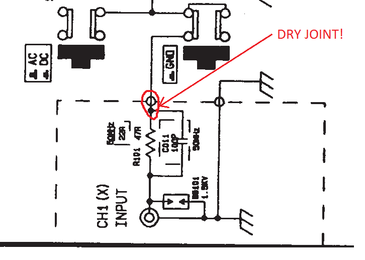 |
| Channel 1 input to Attenuator |
 |
| In Fault condition showing no HT Voltage |
 |
| No Fault condition showing HV available. |
 |
| High Voltage Circuit for CRT supply showing the Oscillator and Step-Up transformer |
 |
| Voltage Divider Calculations. How to measure 2100 volts with a 1000 volt DMM |
13 June 2013
Elephant Speak. Infra-sound Detector
In a recent discussion with my brother-in-law he mentioned that it would be neat to be able to detect elephants communicating with one another. Apparently elephants use so called infra sound frequencies to achieve this interesting form of communication. This is a band of frequencies in the range of 4Hz - 30Hz. A band of frequencies lower than can be detected by the human ear. A search on the web found one particular paper written on the subject by some members of the University of Colombo School of Computing. This design uses a woofer speaker as the detecting device since a woofer will be more closely matched to the long wavelength infra-sound frequencies than a microphone which is of course optimized for the higher audio frequencies.
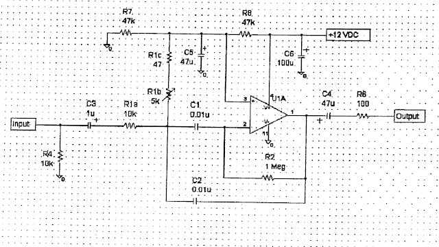
As a prototype I have built a DC coupled inverting amplifier and 2 pole butterworth low pass filter. See the details in the attached diagram below. I have set the amplifier gain at 270 and the filter cutoff frequency at 100Hz. The circuit drives a milliamp meter.
Since I don't have a woofer to hand I simply used a pair of coil movement headphones as the sensor. Initially I tried to couple the sensor into the amplifier using a power transformer. This was interesting. The transformer is meant for transforming 240VAC to 12VAC. This provides a 20:1 turns ratio. Thus I could achieve a 400 times impedance transformation. This higher input impedance to the amp meant that the amp was extremely quiet. No noise floor could be detected in some earplugs which I connected to the output of the amp. I was easily able to hear loud audio in the earplugs from the earphone 'microphone'. The circuit exhibits excellent sensitivity. The problem is that the high input impedance and the transformer picks up significant hum. So while the amp is 'noiseless' the hum is problematic. I tried putting the transformer in a metal container and screening the cable, however I was unable to eliminate the hum.
In the end I settled for connecting the mic directly to the amp via a 1000ohm input resistor. This circuit is definitely noisier than the transformer coupled circuit. However there is no hum and the circuit is well behaved. I set the gain to 270.
Then I built a 2 pole filter as per the diagram below. This appears to be working. There is no detectable noise and the system appears quite sensitive to low frequencies. The lack of noise certainly points to the filter working. I need to look at the performance on an oscilloscope (which I don't have) to really understand how it is performing. I am able to drive a 500mA meter to FSD by scratching the earphone diaphram.
Next Steps:
In a recent discussion with my brother-in-law he mentioned that it would be neat to be able to detect elephants communicating with one another. Apparently elephants use so called infra sound frequencies to achieve this interesting form of communication. This is a band of frequencies in the range of 4Hz - 30Hz. A band of frequencies lower than can be detected by the human ear. A search on the web found one particular paper written on the subject by some members of the University of Colombo School of Computing. This design uses a woofer speaker as the detecting device since a woofer will be more closely matched to the long wavelength infra-sound frequencies than a microphone which is of course optimized for the higher audio frequencies.
As a prototype I have built a DC coupled inverting amplifier and 2 pole butterworth low pass filter. See the details in the attached diagram below. I have set the amplifier gain at 270 and the filter cutoff frequency at 100Hz. The circuit drives a milliamp meter.
Since I don't have a woofer to hand I simply used a pair of coil movement headphones as the sensor. Initially I tried to couple the sensor into the amplifier using a power transformer. This was interesting. The transformer is meant for transforming 240VAC to 12VAC. This provides a 20:1 turns ratio. Thus I could achieve a 400 times impedance transformation. This higher input impedance to the amp meant that the amp was extremely quiet. No noise floor could be detected in some earplugs which I connected to the output of the amp. I was easily able to hear loud audio in the earplugs from the earphone 'microphone'. The circuit exhibits excellent sensitivity. The problem is that the high input impedance and the transformer picks up significant hum. So while the amp is 'noiseless' the hum is problematic. I tried putting the transformer in a metal container and screening the cable, however I was unable to eliminate the hum.
In the end I settled for connecting the mic directly to the amp via a 1000ohm input resistor. This circuit is definitely noisier than the transformer coupled circuit. However there is no hum and the circuit is well behaved. I set the gain to 270.
Then I built a 2 pole filter as per the diagram below. This appears to be working. There is no detectable noise and the system appears quite sensitive to low frequencies. The lack of noise certainly points to the filter working. I need to look at the performance on an oscilloscope (which I don't have) to really understand how it is performing. I am able to drive a 500mA meter to FSD by scratching the earphone diaphram.
Next Steps:
- Build a 4Hz - 300Hz variable oscillator and amp so that I can generate a test signal and thus get some idea of selectivity, sensitivity and linearity using two woofers (one as the transmitter and one as the receiver) (my sister has two medium range speakers which I will try next).
- Find some elephants.
The Future
If the prototype works then there are many applications and advancements that can be implemented. The most value-add would be to interface the detector to an A/D converter so that digital signal processing can be applied. The Colombo University project utilized a 44KHz samples/second fourier transform technique which would yield the elephant language patterns. Now that would be exciting to research!
 |
| Prototype 1 _ Infrasound detector |
 |
| Prototype 1 Infrasound detector |
05 June 2013
A visit to ZS6AJY
I paid a most enjoyable visit to OM Barrie, ZS6AJY and his XYL, yesterday afternoon. Barrie is an avid and highly active radio ham, having received his licence 60 ago. I cannot even start to imagine the depth of knowledge Barrie has when it comes to radio!
Barrie showed me around his well appointed shack and antenna farm. Naturally being a CW man (in fact at one time he was a professional telegrapher) he has Ten Tec vintage gear. Until recently he also operated a full station of home brewed equipment.
He also uses an old time bug and a South African post office key. I sent a few characters with this old key and immediately fell in love with it. Barrie has a collection of fine keys including a McElroy bug.
His main antenna consists of an Inverted Vee 40m, and 80m loaded antenna, plus a fan dipole for 20m and 15m. I was also interested in the installed field strength meter near the antennas.
Barrie was, until recently, a keen home brewer. He still has a number of rigs in his possession including DC Receivers, Transmitters and Control circuits plus an excellent range of homebrewed test equipment. He truly embodies the spirit of QRP home brew and what ham radio is all about. Barrie kindly passed on a number of valuable parts and books to me during my visit. These will help me greatly in my own home brew projects. Many thanks Barrie and I look forward to many more FB CW QSO's with ZS6AJY.
I paid a most enjoyable visit to OM Barrie, ZS6AJY and his XYL, yesterday afternoon. Barrie is an avid and highly active radio ham, having received his licence 60 ago. I cannot even start to imagine the depth of knowledge Barrie has when it comes to radio!
Barrie showed me around his well appointed shack and antenna farm. Naturally being a CW man (in fact at one time he was a professional telegrapher) he has Ten Tec vintage gear. Until recently he also operated a full station of home brewed equipment.
He also uses an old time bug and a South African post office key. I sent a few characters with this old key and immediately fell in love with it. Barrie has a collection of fine keys including a McElroy bug.
His main antenna consists of an Inverted Vee 40m, and 80m loaded antenna, plus a fan dipole for 20m and 15m. I was also interested in the installed field strength meter near the antennas.
Barrie was, until recently, a keen home brewer. He still has a number of rigs in his possession including DC Receivers, Transmitters and Control circuits plus an excellent range of homebrewed test equipment. He truly embodies the spirit of QRP home brew and what ham radio is all about. Barrie kindly passed on a number of valuable parts and books to me during my visit. These will help me greatly in my own home brew projects. Many thanks Barrie and I look forward to many more FB CW QSO's with ZS6AJY.
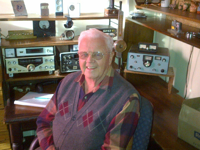 |
| ZS6AJY OM Barrie |
 |
| ZS6AJY's Ten Tec vintage Station |
Subscribe to:
Posts (Atom)