1) The most efficient combination of tuner and counterpoise that will produce greatest RF current in a half wave, end-fed, field deployed, 40m, antenna.
2) Determine the best combination based on received signal reports by ZS4SF based in Welkom.
3) Determine the difference in signal strength between the best and worse case.
PROCEDURE: refer to the attached detailed schematic and pictures showing:
1) Test configuration.
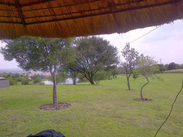
2) Local conditions at the test site
3) Receiving station ZS4SF details
4) The 3 tuner details
5) The test results


GENERAL CONCLUSIONS
1) The combination of the 'Granadilla' tuner and 17ft counterpoise produced the best 'stable' result showing a marginal single S point improvement of 569 over the average signal reports of 559 using 2 Watts transmitter output.
2) The combination in 1) above also showed good consistent output on the RF current meter although the combination of the Granadilla tuner and 8.5Ft counterpoise showed a higher RF current, however the setup was unstable and variable.
3) The Z Match showed the worst performance of the 3 tuners with all 3 counterpoises. The DC meter sensitivity control had to be increased in order to obtain an RF current report. However 559 and 549 signal reports were still received.
KEY CONCLUSION
1) Based on the signal reports from ZS4SF there was a marginal difference of less than 1 'S' point (estimate 4dB) between the best and average cases. Indicating that all combinations are acceptable for real field deployments.
OBSERVATIONS
1) It was difficult in a real field deployment to get a consistent RF current measurement with the output varying depending on proximity effects.
2) None of the combinations were completely stable indicating that tweeking is required to reduce the ground currents and to obtain a resonant antenna with minimum reactance present. (difficult to achieve in the field).
PROXIMITY AFFECTS
1) Upon terminating the Granadilla tuner on the bench with a 4.7K resistor after the field tests, it was determined that the resonant frequency was at 7.487MHz. This is 7.487 - 7.020 = 467KHz difference. Assuming the tank circuit inductor is fixed at 4uH, this reveals a capacitive contribution of 16pF from the antenna/counterpoise system contribution. If this contribution came entirely from the antenna wire then the effective antenna length can be calculated as 71.4ft (as opposed to 66.66ft actual length). This seems to be a big difference in length and may explain why the system was unstable during the tests.
GRANADILLA TUNER ADVANTAGE
The Granadilla tuner has two key differences when compared to the Altoids tuner. It uses an Air variable panel mounted, screw driver adjustable, 30pF capacitor, in parallel with a 10pF silver mica capacitor with a 500V rating. The Altoids tuner uses a 150pF polyvaricon capacitor. Both tuners use the same T-50-2 inductor. The Z Match utilizes two polyvaricon capacitors. Could it be the polyvaricon capacitors that exhibit losses in this environment.
Assuming a radiation resistance of 3000Ohms and 2 watts, the peak-to-peak voltage across the tank circuit = SQUAREROOT( 8 X P X R) = SQUAREROOT(8X2X3000) = 219Volts. Does this voltage stress the polyvaricon capacitors?
This was a fun project and very instructive! My thanks to my friend OM Monk in Welkom ZS4SF for hanging in there and providing 12 signal reports. Thanks Monk! 73.
 |
| Z Match, Granadilla Tuner, Altoids Tuner |
 |
| View of the RF current sensor connected to a sensitive DC analog meter (0-1mA) |
 |
| View of Antenna, Cedar Lakes upper picnic table, Fourways, Gauteng, South Africa |
 |
| Granadilla in South Africa is known as passion fruit in the USA. Yummy! |
 |
| The 7020Khz capacitor pure resistive position terminated in a 4.7K resistor. Antenna reaction is tuned out in the field. |
No comments:
Post a Comment